A whole decade ago (wow!) I read a blog post called “A Modern Space Cadet” and… well, started caring about keyboards. I’ve adopted quite a few of the software tricks right there and then: shifts-as-parens and capslock-as-control-and-escape.
The hardware part—the whole mechanical keyboard thing—took me a couple years to get to. I was only using a MacBook Air when the post came out, but eventually as I got a desktop, I had purchased my first mech which was a Leopold with original Cherry MX Brown switches. I’ve used it for several years, but eventually I found myself wanting more. Specifically, clicky switches and the ergonomics of the split form factor. In 2020 I purchased this AliExpress split keyboard from a manufacturer called “Spider Island”. I’ve ported QMK to it, because of course. It felt like a nice upgrade at the time, though the clone MX Blue switches weren’t the highest quality (as in, a couple started having weird phantom actuations) and the SATA cable connection between the halves being flaky was annoying.
Around the end of 2021 I was looking at higher quality split options like the Dygma Raise and the ZSA Moonlander and… decided that I was too weird for either of them and would rather spend money on fabrication and parts for something fully custom. I think this video might have been the final inspiration.
So, I started thinking about what I actually wanted and came up with this list of requirements:
- column-staggered layout like the famous ErgoDox
- nice clicky switches (after some YouTube-watching the choice was clear: Kailh Box Jade!)
- “floating key” enclosure design (why is that the common term anyway? I always wanted to call it “borderless”! because it doesn’t have a border, come on!)
- for connections: USB Type-C to the host, anything reliable between the halves
And a list of extra “wants”:
- volume control knob (easy)
- pins for connecting external buttons like a big red panic button or a vim pedal
- a magnetic connector for add-on modules like trackballs, like on the UHKB?
- a 3.3V TTL output-only serial port header, for a “teletype mode” i.e. directly typing into the UART of something like an RPi?
- maybe analog input on WASD keys for gaming too?
Spoiler alert: I didn’t successfully implement all the experimental stuff :) But I’m really happy with the result!

So, here’s how we got there…
Learning PCB design
The first thing you need to make a PCB-based keyboard is, well, being able to design PCBs! So I watched a KiCad tutorial on YouTube to learn and… did not start using KiCad. Because you see, I have a terminal case of hipster-ism :) So I started to play around with the far less popular Horizon EDA instead and it was an absolute dream. What a beautiful, coherent, smart piece of software.
Before actually going for the full keyboard, I’ve decided to make a proof-of-concept: a little dev board basically containing what would be the brain of the keyboard (I picked the STM32L1 family because it was less affected by the chip shortage and, you know, power-saving sounds good) and pins. Tiny boards are a lot cheaper to manufacture, so if something went wrong, it wouldn’t be that much of a loss. So I designed it, uploaded it to JLCPCB, paid some money and… success! It worked perfectly!

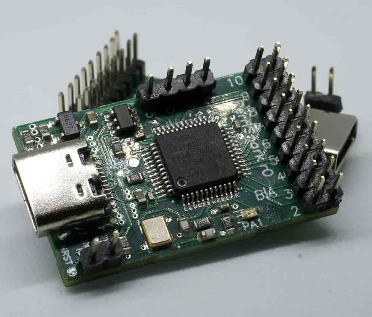
I called this board Ferrispark as a reference to Ferris the Rust mascot and Digispark, the board whose form factor (18×29 mm) this one fits in. With that little thingy in hand, it was possible to experiment with firmware stuff while waiting for the keyboard PCB to be manufactured and shipped. But first…
Layout
Unlike “normal” keyboards that come with boring standard ANSI/ISO layouts, enthusiast keyboards are very diverse, and with a fully custom build possibilities are truly endless. One can try to get away with very few keys or make an unhinged meme board or whatever. But I was after something practical, tailored to my habits, based on ergonomic innovations but not too different from standard layouts.
So I opened everyone’s favorite non-FOSS (boo) layout editor web app, loaded the Ergodox preset, removed all the unassigned keys surrounding the core clusters, and started adding keys that made sense to me.
The first thing I added was two columns on the right side that kinda just bring back the punctuation as it is on ANSI.
This felt really important to me because it’s not just about keeping the habits regarding the {[<:;'">]} stuff.
Some non-Latin scripts such as Cyrillic have a lot of letters, so those two columns have actual letters on them when typing those.
Coming up with alternatives (like chords) for that seemed like more of a nightmare than just for punctuation.
By the way, I added these columns without shifting them down, so they ended up as a 3-wide ortholinear grid cluster on the right end of the layout —
I quickly realized that it would be a good fit for a numpad on an alternate layer too!
Then I started adding modifiers and other miscellaneous keys. I’ve added shifts where my fingers expect them to be (since I use shifts-as-parentheses, the “just one shift key” idea from minimalist boards is really not for me). For the thumb clusters, I’ve added the most important text actions—Space, Tab, Backspace, Return—as large keys. I’ve added a dedicated actual Compose key because I use one. Then I started noticing that the key count was climbing up. Dangerously close to a funny number, even. So I’ve added four extra “macro” keys, some really extra stuff like “menu”, and ended up with exactly 69 keys. That instantly solved the hard problem of naming things: the board was called “ErgoNICE” from that point on! :) Here’s how the layout looks:

(This is the physical layout, so you see QWERTY here. I actually type on Colemak though!)
PCBs
Before actually designing the PCB, I started looking at existing keyboard designs (nearly all in KiCad), importing various parts into Horizon, purchasing extra components like the rotary volume knob and headphone jacks on AliExpress and modeling them in Horizon, and otherwise doing various preparations.
Keyboard PCBs aren’t rocket science. There are basically two ways to connect the keyswitches to the MCU: in a matrix and directly. With a compact split keyboard, direct is more feasible than ever, you don’t even need that huge of a microcontroller, so I actually saw that solution in one of the designs I was looking at. But my choice of MCU was somewhat limited by the chip shortage, and my board wasn’t that compact, and I wasn’t looking forward to routing all the direct connections with just 2 layers (which was the limit for non-green boards on JLCPCB and I just waaaanted a black one even though it won’t be visible), so the obvious decision was to go with a matrix with diodes on every switch.
The other decision I made early on was that the left half would contain the microcontroller and would be assembled by JLCPCB with a ton of SMD parts, while the right one I would entirely hand-solder at home, using parts I already owned when possible. And that would be… through-hole diodes and the MCP23017-E/SP input/output expander. Yeah, the DIP package variant. Because that’s what I purchased about 10 years ago (!) from an Arduino stuff store when I was first experimenting with electronics. How convenient!
Speaking of diodes, something I saw and really liked was this footprint for either a surface-mount or through-hole diode. However you can’t just import that straightforwardly into Horizon. KiCad is fine with multiple pads/holes sharing a name, and will just collapse them into one pad. Horizon is a lot more strict: each pad must have its own unique name, and if you want to construct something fancy like that, you need to do it inside of a padstack. Thankfully, Horizon’s parametric padstack system is extremely capable. It’s based on a little stack-based scripting language for repositioning everything based on whatever logic you want. However it was missing the ability to reposition holes from the script, so I’ve had to add it, and then:

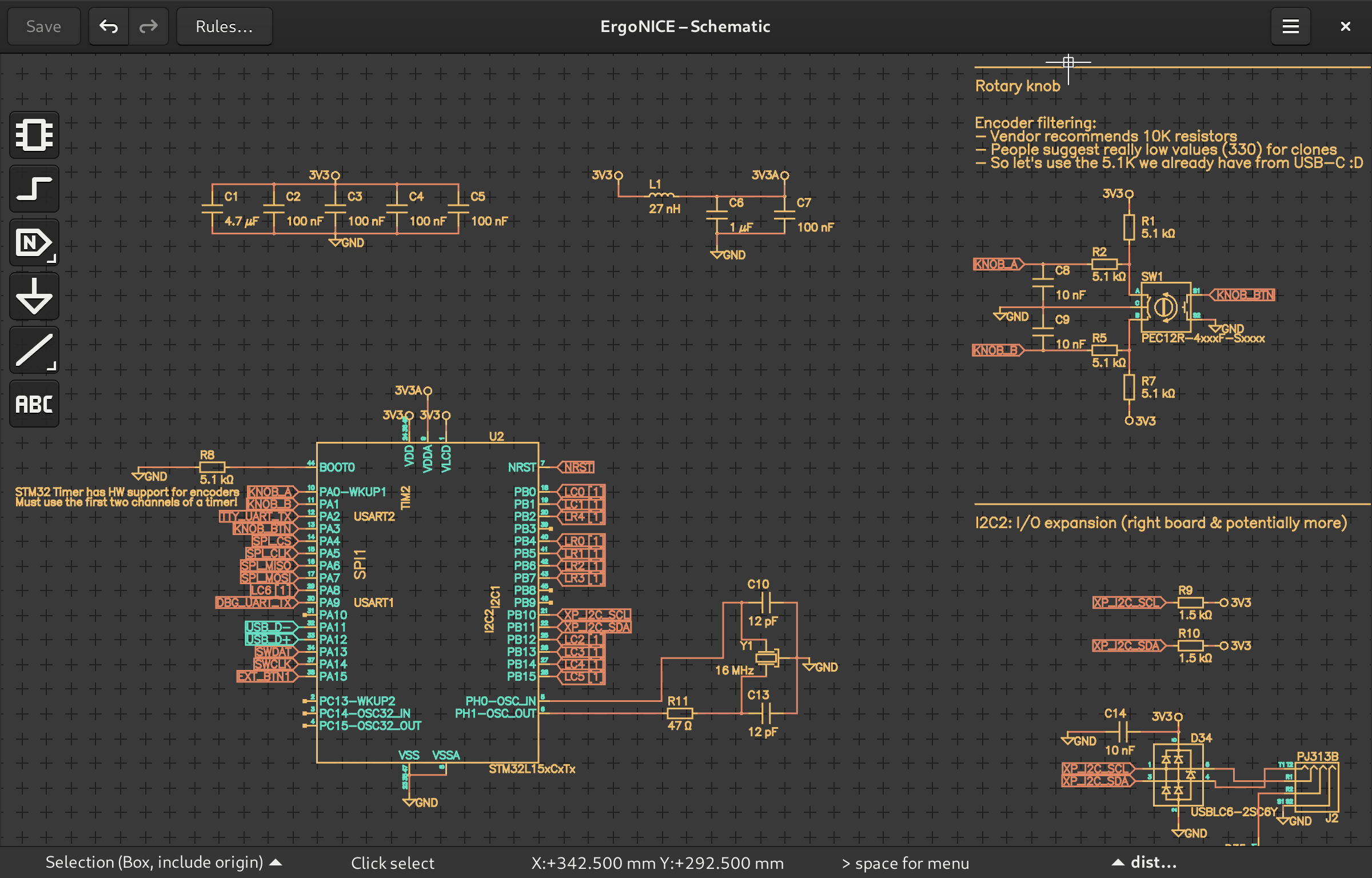
So. Anyway. Actual keyboard design time. You can view the full schematic as a PDF here. There’s not that much to say: it contains the aforementioned matrix (well, two of them, left and right), the microcontroller and everything it requires, the USB-C connector with correctly separated CC resistors, TRRS audio connectors, various pin connectors (debug header, extras like external buttons), the rotary knob with required circuitry… oh, and a bunch of various protection. Even though I’ve noticed that various DIY keyboard designs don’t seem to do much of it, I was really into the idea of extra safety, so I put resistors on all the external-facing pins, transistors for reverse polarity protection on power inputs, a USBLC6 IC on the USB lines, and so on.
Layout started with feeding the JSON output of the keyboard-layout-editor website to another website, Keyboard CAD Assistant. It produces DXF files that are supposed to be used for cutting a plate on a CNC router, but I actually needed it for the PCB. I’ve imported the DXF into Horizon EDA, drew polygons with diagonals over each key square, and got precise centers of each key — exactly what’s necessary to position the keyswitches!
Then I drew the outlines of the halves, positioned all the other components, routed the tracks… everything as expected. Routing can be quite fun, especially when the EDA tool looks this nice (this is the “Rust” color scheme, ha):

After getting pretty confident that the board was correct (the design rules check in Horizon is pretty helpful!) I’ve sent it off to manufacturing. A couple weeks later, I received the exciting notification from the post office. The long-awaited package from China!


Here’s a comparison with the 3D preview in Horizon. The real thing always looks amazing!


If you want to play around with the PCB design files in Horizon EDA yourself, it’s in the pcb-ergonice directory in the repo.
And in the release downloads, there is an export with Gerber files and BOM/CPL for assembly.
Disclaimer: the revision 1 which is published there is slightly different from the revision 0 which I physically have built. Keep reading to see the bug that I fixed there!
Analog input?
Analog keys are a pretty fun thing for gaming, allowing you to move slowly in CS for example. I stumbled upon these people here that were trying to commercially sell add-on flex PCBs for adding the capability to an otherwise normal keyboard and began wondering if it’s possible to just DIY it. It seems to be a bit of a scary topic because they have a patent in some jurisdictions, but who would go after a non-commercial personal project? So, their technique is just using a Texas Instruments inductance to digital converter with a PCB coil. Luckily, these chips were easily available on JLCPCB’s assembly service (though not cheap), so I just went ahead with the experiment. That is, I designed a little “evaluation board”, suspiciously shaped to fit under the keyboard PCB’s WASD cluster and connect to it using 2.54mm headers :)
The interesting part of the design process is of course the PCB coils. TI provides an online tool for generating them. It supports some export… into a couple commercial EDA tools. But I found a way get the results into Horizon. Get this: export as an EAGLE project, open that in KiCad, export the coil as SVG, clean it up in Inkscape (merge into one SVG path), export as DXF R12, and finally import into Horizon with a downscaling factor of 10000 because reasons. Oof, it’s there! But we can’t connect anything to it, because it’s just lines, not tracks. And somehow they’re not even all connected.
Naturally, this was an opportunity to dig into Horizon EDA’s codebase and add some new tools! This was a very enjoyable experience, and with some quick feedback from the author of Horizon I split one of the tools into two, and here they are: “select connected lines”, “merge duplicate junctions”, and “lines to tracks”. With Horizon becoming this much better, the board was easy to make. This is how it looked:


To try it out, I wrote a Rust embedded-hal driver for the LDC1x1x chips and an embedded-hal implementation for FreeBSD userspace APIs so that I could test it directly on my PC with a CP2112 USB-to-I²C adapter, just piping the output from a demo program into ploot.
What I’ve found is that while the stream of numbers was indeed correlated with how far the key was pushed down, it was not good. Whether I was catching the movement of the finger or the spring was pretty confusing, especially when under the actual keyboard PCB. The fact that the switches of my choice have a click bar might’ve been a negative impact, the distance to the switch from behind of the PCB was probably a problem, and the large 4-layer coil probably wasn’t quite compensating for that (or was it actually just bad?).
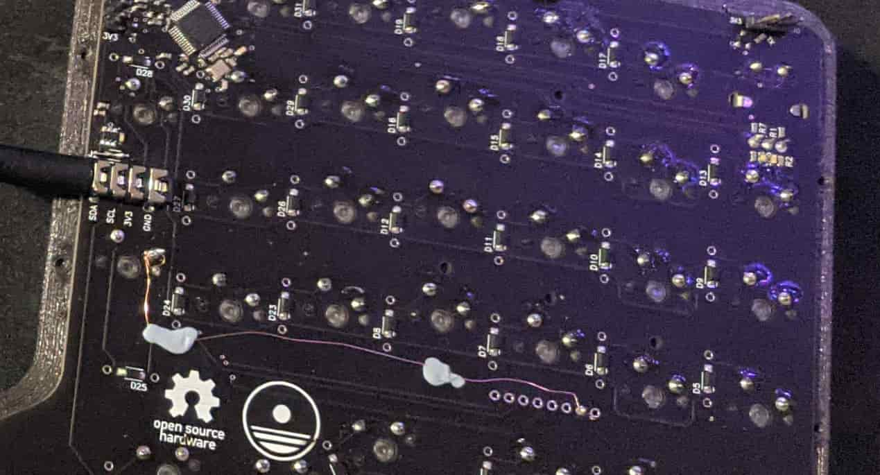
Either way, I couldn’t attach it to the keyboard because it turns out I’ve made a silly mistake in the schematic: I forgot to connect one of the columns to the microcontroller :D So I ended up running a bodge wire to one of the holes intended for the LDC board:
Case
There are many ways to make a keyboard enclosure, but as I was into 3D printing, that question was already answered. How convenient that a split keyboard fits well into the dimentions of an Ender 3 build plate! I’ve been using realthunder’s FreeCAD fork for modeling 3D printed parts, so that’s what I used for this one as well. Of course FreeCAD’s UI is clunky and its core is crashy, but I’d rather not involve proprietary software in this project. Having CAD files in an open format is that valuable to me. And before someone starts preaching code-CAD like cadquery to me: sorry, I love sketching with a mouse and hate school-style math too much :D
I started out with exporting a 3D model of the boards and components on them as a STEP file from Horizon and importing it into FreeCAD. In the file, everything was cleanly separated out, i.e. each component was its own body. However due to format limitations every instance of the same part (e.g. every switch) is its own independent body, which takes up a lot of space on disk. I wrote a Python script in FreeCAD that would take the currently selected bodies and replace all of them except the first one with a link to the first one, removing the duplication of actual 3D model data. (Sadly I lost that script by now, but it was tiny.)
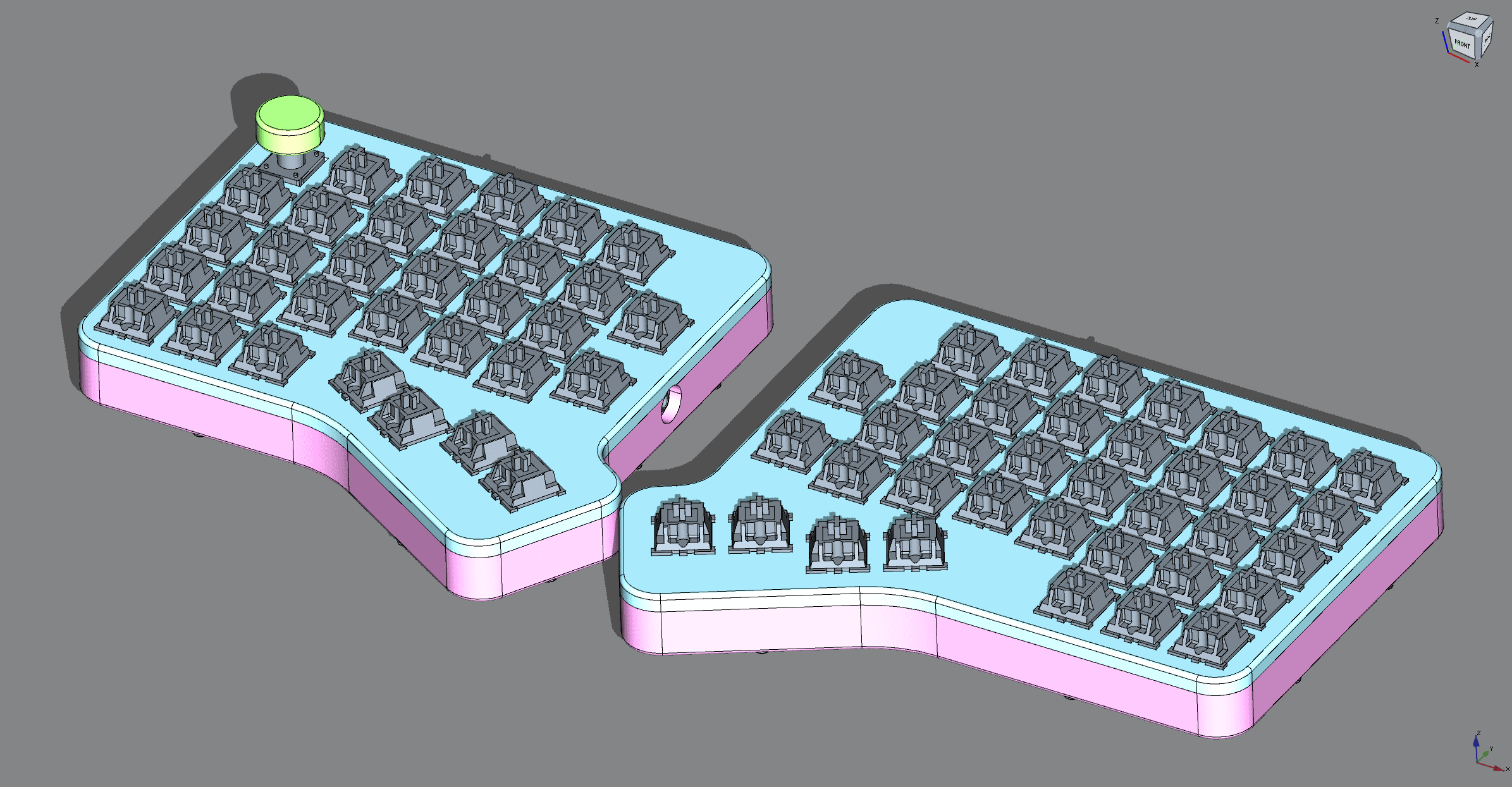
With a model of the boards, it wasn’t too hard to make an enclosure around them. The enclosure has two main parts. The plate is a flat extrusion that gets permanently attached between top of the PCB and the bottom halves of the switches. The tray is the rest of the enclosure, attached to the plate with screws. In addition there are tenting wedges that attach to the bottom of the tray, and the actual knob that goes on the rotary encoder. This is how it all looks in FreeCAD:

Here’s a look into the tray from the above. I’ve added these supports underneath each key for extra rigidity. Otherwise it’s… not that remarkable?

I printed the parts on a heavily modified Ender 3 Pro out of dark gray sparkly PETG. It turned out pretty well! Everything fit together easily, the tolerances for things like the space for the key switches were exactly right, it looks very decent for a DIY object. Again, this is how it looks:
If you want to play around with the source model, it’s all of that XML in the case directory
stored in the repo, saved using the version-control-friendly “save as directory” functionality of realthunder’s FreeCAD.
And in the release downloads, there’s an archive with STL and STEP exports.
Firmware
Now that everything is put together physically, we need to put software on the tiny little computer that runs the keyboard (it’s computers all the way down!).
The most common way to get some keyboard firmware going is to use a popular project like QMK (a classic that started on AVR and added Arm later) or ZMK (popular with Bluetooth, based on a whole RTOS called Zephyr and configured with flattened device trees). But of course, “common way” means it’s not what I’m going to do.
Rust on STM32L1
I like the Rust programming language quite a lot and it’s, like, good for embedded so of course I’m going to use it here. Naturally, I’m not the only one doing so: I was quite happy to discover that there was already a library called Keyberon for handling all the uhh… keyboarding.
Now, how does the Rust ecosystem for STM32 look like?
Unlike the C world where you interact with one monolithic SDK (either the vendor-provided one or libopencm3)
there is a lot more code sharing and integration due to the magic of package management.
The “libopencm3” of Rust is spread over a variety of crates: the center of that vague “SDK” is
interface crates like embedded-hal and usb-device,
and there are both drivers that use those interfaces and microcontroller support crates such as the stm32-rs ones that implement them.
There is however the “parallel ecosystems” thing too, but not because of vendors: the rather standalone world here is
Embassy, an async embedded framework.
And in fact, because stm32-rs’s stm32l1xx-hal is not actively maintained, I’ve considered using Embassy for the project.
I played around with it, fixing some STM32L1 initialization code and stuff,
but ultimately ended up just forking stm32l1xx-hal, adding USB support and I²C timeouts and of course fixing bugs.
With a reasonable HAL crate and Keyberon in hand, it’s pretty straightforward to put the pieces together. But I didn’t do anything in the straightforward way because I can get kinda obsessed with efficiency :)
STM32 Hardware Magic
The cool thing to do for efficiency in embedded development is to let hardware do things as much as possible instead of software.
The first opportunity to leverage nice STM32 peripherals is of course the volume knob: the hardware timers have the ability to read a rotary encoder instead of, well, counting time. As long as you connect the encoder to a pair of pins that do correspond to a timer, which I did as I knew this beforehand, at the PCB design stage. So in the code, grabbing the timer for this purpose is as simple as:
let knob_cnt = cx.device.TIM2.qei((gpioa.pa0, gpioa.pa1), &mut rcc);
And when polling all the things, we simply check if the count has increased or decreased since the previous time we did that, and by how much. Depending on that, we press-and-release a designated key position in the layout, where we place volume up / volume down keys on the main layer and other fun stuff on other layers (e.g. I made it so that Fn+knob is scroll up / scroll down, just for fun).
let knob_now = cx.local.knob_cnt.count() as i16;
let knob_row = if knob_now > *cx.local.knob_last { 1 } else { 0 };
for _ in 0..(knob_now - *cx.local.knob_last).abs() / 2 {
    handle_event::spawn(layout::Event::Press(knob_row, (LCOLS + RCOLS) as u8)).unwrap();
    handle_event::spawn(layout::Event::Release(knob_row, (LCOLS + RCOLS) as u8)).unwrap();
}
*cx.local.knob_last = knob_now;
Now, how about something more advanced? But what is left there to automate? Well, of course, the actual reading of the keyboard matrix! It’s a common thing, there should be hardware solutions! And there are. There are ICs that do keyboard matrix scanning (usually I/O expanders with that functionality), the Programmable I/O peripheral of the RP2040 might be promising for this application, of course cool things can be done with FPGAs (you can make a microcontroller with your own key scanner peripheral like in the icekeeb project). But it turns out our little STM32 already has a great tool for the job!
Because… it can DMA between memory and banks of GPIO pins, triggered by a timer. When I was thinking about the DMA capabilities, I was wondering if someone has already done what I wanted to do and yes! This 2016 blog post describes exactly how to do it. (With some bonus big-brain thoughts on key debouncing.) This part of the post sounded somewhat worrying:
Allocate all row output pins on one GPIO port and all column input pins on another GPIO port
as I have not done that on my PCB. But well, I quickly realized that I could extend this idea to work with pins arbitrarily scattered across both of the two pin banks, just by using more timers. But my job was slightly easier as only columns (outputs in my design) were in both banks, A and B, while rows (inputs) only were in bank B.
Here's how the Rust magic for that looks
To generate the bit patterns, I used a const fn:
const fn gen_gpio<const N: usize>(pins: [i32; N]) -> [u32; N] {
    let mut result: [u32; N] = [0; N];
    let mut p = 0;
    while p < N {
        if pins[p] >= 0 { result[p] = 1 << pins[p]; }
        p += 1;
    }
    result
}

static mut IN_GPIOB: [[u32; LCOLS]; 2 * BOUNCES] = [[69; LCOLS]; 2 * BOUNCES];
static OUT_GPIOA: [u32; LCOLS] = gen_gpio([-1, -1, -1, -1, -1,  8, -1]);
static OUT_GPIOB: [u32; LCOLS] = gen_gpio([ 1, 12, 13, 14, 15, -1,  0]);
Okay, not that cool, it’s a rather verbose way to avoid writing 1 << everywhere, but I’m a big fan of
compile-time function execution.
But more to the point, the memory layout already explains how the DMA setup works.
On every tick, the next output configuration will be selected across both GPIO ports (activating the next column)
and the next readout of the inputs (well, of all the inputs on bank B) will be put into memory.
For configuring the DMA engines, which don’t have friendly wrappers in the HAL crate, I wrote a macro wrapping the raw hardware register writes to make it look decent like so:
dma_chan! { dma1: // TIM4_CH1 -> DMA1_CH1
    cndtr1 [LCOLS]     cmar1 [&OUT_GPIOB as *const _]
    cpar1 [gpiob_odr]  ccr1 [mem2per nointr]
};
dma_chan! { dma1: // TIM3_CH3 -> DMA1_CH2
    cndtr2 [LCOLS]     cmar2 [&OUT_GPIOA as *const _]
    cpar2 [gpioa_odr]  ccr2 [mem2per nointr]
};
dma_chan! { dma1: // TIM3_UP -> DMA1_CH3
    cndtr3 [LCOLS * BOUNCES * 2]  cmar3 [&mut IN_GPIOB as *mut _]
    cpar3 [gpiob_idr]             ccr3 [per2mem intr]
};
So, the output channels just cycle through the very short 7-element arrays, enabling only one column at a time.
The input reading channel is the interesting one.
The * 2 in the array length is related to DMA double buffering.
See, the engine can interrupt the CPU both when it goes through the entire array and wraps around,
and right in the middle of the array. This allows the CPU and the DMA engine to avoid stepping on each other’s feet:
on the half interrupt we read the first half of the memory, and on the full interrupt we read the second one.
And yeah, each half contains a few readouts in a row, to be fed into a debouncer.
This is how it’s done, converting the raw GPIO readout bytes into a matrix for Keyberon:
static ROW_GPIOS: [u32; ROWS]  = gen_gpio([4, 5, 6, 7, 2]);
let is_half = dma1.isr.read().htif3().bit();
let scans = unsafe {
    &IN_GPIOB[if is_half {
        0..BOUNCES
    } else {
        BOUNCES..2 * BOUNCES
    }]
};
for scan in scans {
    let mut mat = [[false; LCOLS]; ROWS];
    for (c, colscan) in scan.iter().enumerate() {
        for (r, rowmask) in ROW_GPIOS.iter().enumerate() {
            mat[r][c] = (colscan & rowmask) != 0;
        }
    }
    for ev in cx.local.debouncer_l.events(matrix::PressedKeys(mat)) {
        handle_event::spawn(ev.transform(left2global)).unwrap();
    }
}
And… it works! Now, of course I haven’t measured any efficiency gains versus doing everything the basic software way :D But having fun with the implementation was the point more than anything.
The entire source of the firmware is in the fw directory in the repo.
Things not done
Of course the end result ended up less ambitious than the initial project. Out of the initial list of ideas, the analog input fell out at the PCB stage, while the extra peripheral (trackball/etc.) support kinda fell out at the case design stage. The “teletype mode” via the output-only serial port header only fell out here at the firmware stage though, with potential to come back and add it someday.
However there’s another thing I was rather interested in but didn’t get to try in the firmware, and that is USB Selective Suspend which should allow the microcontroller to go to sleep for idle periods. This isn’t easy to accomplish, but it seems like resuming the USB connection after sleep on the STM32L1 series might be possible.